
News detail
Knowledge Sharing | MCU Memory Allocation
Detailed Explanation of MCU Instruction Execution: The process by which an MCU executes a program is actually the process of executing the program we have written—that is, executi…


The process by which an MCU executes a program is actually the process of executing the program we have written—that is, a process of executing instructions one by one. Each time a computer executes an instruction, it can be divided into three stages: fetch instruction—analyze instruction—execute instruction.
The task of instruction fetch is to read the current instruction from program memory according to the value in the program counter (PC) and send it to the instruction register.
The task of the instruction analysis stage is to extract the operation code from the instruction in the instruction register, decode it, and analyze the nature of the instruction. If the instruction requires an operand, the operand address is located.
The process by which a computer executes a program is actually repeating the above operations instruction by instruction until it encounters a halt instruction or can enter a loop waiting for an instruction.
When a general-purpose computer operates, it first needs to transfer the program and data through external devices, via the input interface circuit and data bus, into memory, and then fetch and execute them one by one. However, for a microcontroller, the program is generally pre-programmed by us through a programmer into on-chip or off-chip program memory in advance. Therefore, instructions can be executed as soon as the device is powered on.

Below, we will give an example to illustrate the instruction execution process:
At power-on, the program counter (PC) becomes 0000H. Then, under the action of the timing circuit, the microcontroller automatically enters the program execution process. The execution process is actually a cyclic process of fetching instructions (the stage of fetching the instructions previously stored in memory) and executing instructions (analyzing and executing instructions).
For example, to execute the instruction: MOV A, #0E0H, its machine code is “74H E0H”. The function of this instruction is to send the operand E0H to the accumulator. Address 0000H already stores 74H, and address 0001H already stores E0H. When the microcontroller starts running, it first enters the instruction fetch stage. The sequence is:
1. The content of the program counter (at this time 0000H) is sent to the address register;
2. The content of the program counter is automatically incremented by 1 (becomes 0001H);
3. The content of the address register (0000H) is sent to memory via the internal address bus; through the address decoding circuit in memory, the unit with address 0000H is selected;
4. The CPU makes the read control line active;
5. Under the control of the read command, the content of the selected memory unit (which should be 74H at this time) is sent to the internal data bus. Because this is the instruction fetch stage, this content is sent via the data bus to the instruction register.
At this point, the instruction fetch stage is complete, and the instruction enters the decode/analyze and execute stage.
Since the content that entered the instruction register this time is 74H (the operation code), after decoding by the decoder, the microcontroller knows that this instruction is intended to send a number to accumulator A, and that number is in the next memory unit after this code. Therefore, to execute this instruction, the data (E0H) must also be fetched from memory and sent to the CPU—that is, the second byte must also be fetched from memory. The process is very similar to the instruction fetch stage, except that PC is now 0001H. The instruction decoder, together with the timing unit, generates the micro-operation sequence for the 74H operation code, causing the number E0H to be fetched from unit 0001H.
Because the instruction requires the fetched number to be sent to accumulator A, the fetched number enters accumulator A through the internal data bus rather than the instruction register. At this point, execution of one instruction is complete. In the microcontroller, PC = 0002H. PC is automatically incremented by 1 each time the CPU fetches an instruction or data from memory. The microcontroller then enters the next instruction fetch stage. This process repeats continuously until a pause instruction or a loop-wait instruction is received to pause. In this way, the CPU executes instructions one by one and completes all specified functions.
For an MCU, when describing its performance, the capacity of SRAM and Flash is always stated. For beginners, these things are not usually considered or paid attention to; they just take the device and use it. In fact, this is not the case—these quantities are very important. Think carefully: why can code run, how large is the code, and how are variables of types such as int and short actually allocated and stored? These questions are all related to memory.
First, microcontroller memory can be broadly divided into RAM and ROM. We will not explain the difference between RAM and ROM here; we can equate them to Flash and SRAM. According to the definitions of Flash and SRAM, data in Flash can be retained after power loss, while data in SRAM cannot, but SRAM executes faster than Flash. The microcontroller program can be divided into code (code storage area), RO-data (read-only data storage area), RW-data (read/write data storage area), and ZI-data (zero-initialized data area). In the MDK compiler, the values of these four quantities in the code can be observed, as shown in Figure 1 below:
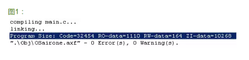
Among them, code and RO-data are stored in Flash, so the sum of the two is the amount of Flash space that the microcontroller needs to allocate to them (and it is equal to the size of the .bin file generated by the code). In addition, RW-data and ZI-data are stored in SRAM; likewise, the sum of the two is the amount of SRAM space that the microcontroller needs to allocate to them.
In addition, we will inevitably think of the relationship between the stack area, heap area, global area (static area), literal constant area, and program code area and the code, RO-data, etc. described above.
1. Stack area: automatically allocated and released by the compiler; stores function parameter values, local variable values, etc. Its operation is similar to a stack in a data structure. These values are readable and writable, so the stack should be included in RW-data (read/write data storage area), that is, in the microcontroller's SRAM.
2. Heap area: generally allocated and released by the programmer. If the programmer does not release it, it may be reclaimed by the OS when the program ends. It can be understood that these are also included in the microcontroller's SRAM.
3. Global area (static area): global variables and static variables are stored together. Initialized global variables and static variables are in one area, and uninitialized global variables and uninitialized static variables are in another adjacent area; they are released by the system after the program ends. These data are also readable and writable, and, like the stack and heap, are included in SRAM.
4. Literal constant area: constant strings are placed here. These data are read-only, are allocated in RO-data (read-only data storage area), and are therefore included in Flash.
5. Program code area: stores the binary code of function bodies. It can be imagined that this is also included in Flash, because for an MCU, when it is powered on again, the code will continue to run and will not disappear, so it is stored in Flash.
Note: This article is reprinted from the Internet., This article is reprintedfor the purpose of conveying more information; the copyright belongs to the original author.

Zhuhai Taixin Semiconductor Co., Ltd.
Founded in 2016, Zhuhai Taixin Semiconductor Co., Ltd. is a high-tech enterprise integrating IC design and wireless intelligent communication solutions. We have successively launched long-range, low-power Wi-Fi chips for the Internet of Things, low-power motor controller chips, and product solutions. The company adheres to a market-oriented approach with technology as its core, providing customers with high-quality chips and product technical solutions.
The company's core product is a long-range, low-power Wi-Fi communication chip for the Internet of Things. This chip can be used in smart home, security monitoring, UAV image transmission, smart meter reading, smart door locks, smart grid, smart hospitals, logistics robots, and other product fields.