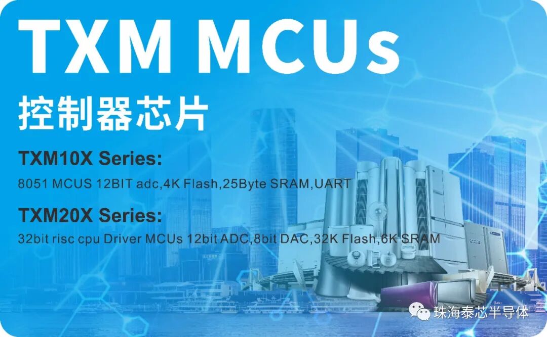

MCU is short for Microcontroller Unit; in Chinese, it is called a microcontroller and commonly known as a single-chip microcomputer. It appropriately scales down CPU frequency and specifications and integrates memory, counters, USB, A/D conversion, UART, PLC, DMA, and other peripheral interfaces—and even LCD driver circuits—onto a single chip, forming a chip-level computer that provides different combinations of control for different applications. MCUs can be found in mobile phones, PC peripherals, remote controls, automotive electronics, industrial stepper motors, robotic arm control, and many other areas.
A Brief History of MCU Development
The history of MCUs is not long, but their development has been rapid. Their emergence and development have largely synchronized with those of microprocessors (CPUs). Since Intel introduced the first 4-bit microprocessor in 1971, MCU development can be roughly divided into five stages to date. The following introduces this history using Intel's MCU development as a representative example.1971–1976
MCUInitial development stage. In November 1971, Intel first designed the 4-bit microprocessor Intel 4004 with an integration level of 2,000 transistors per chip, and equipped it with RAM, ROM, and shift registers, forming the first MCS-4 microprocessor system; it later introduced the 8-bit microprocessor Intel 8008, and other companies subsequently launched 8-bit microprocessors.1976–1980
Low-performanceMCUstage. Represented by Intel's MCS-48 series introduced in 1976, it adopted a single-chip structure integrating an 8-bit CPU, 8-bit parallel I/O ports, 8-bit timer/counters, RAM, and ROM on one semiconductor chip. Although its addressing range was limited (no more than 4 KB), it had no serial I/O, its RAM and ROM capacities were small, and its interrupt system was relatively simple, its functions could meet the needs of general industrial control and intelligent instruments and meters.1980–1983
High-performanceMCUstage. The high-performance 8-bitMCUlaunched in this stage generally featured serial ports, multi-level interrupt handling systems, and multiple 16-bit timers/counters. On-chip RAM and ROM capacities increased, the addressing range reached 64 KB, and some chips even included A/D conversion interfaces.1983–late 1980s
16-bitMCUstage. In 1983, Intel introduced the high-performance 16-bitMCU MCS-96 series. Thanks to its use of the latest manufacturing process, the chip integration level reached as high as 120,000 transistors per chip.MCUadvanced comprehensively to higher levels in integration, functionality, speed, reliability, application areas, and other aspects.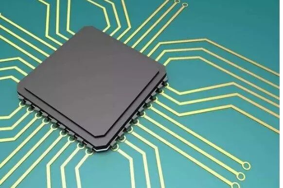
MCU Classification and Applications
By memory type, MCUs can be divided into two types: those without on-chip ROM and those with on-chip ROM. Chips without on-chip ROM must be connected to external EPROM for use (typically the 8031); chips with on-chip ROM are further divided into on-chip EPROM type (typical chip: 87C51), masked on-chip ROM type (typical chip: 8051), and on-chip Flash type (typical chip: 89C51).By application, they can be divided into general-purpose and special-purpose types; by data bus width and the number of data bytes that can be processed at one time, they can be divided into 8-bit, 16-bit, and 32-bit MCUs.At present, the most widespread MCU application market in China is consumer electronics, followed by the industrial sector and the automotive electronics market. Consumer electronics include home appliances, televisions, game consoles, and audio/video systems. The industrial sector includes smart homes, automation, medical applications, and new energy generation and distribution. The automotive sector includes automotive powertrains and safety control systems.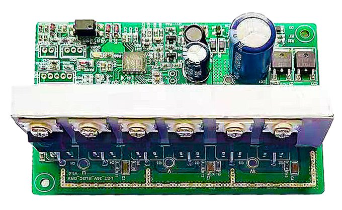
Lawn Mower MCU
Basic Functions of an MCU
For the vast majority of MCUs, the following functions are the most common and fundamental. For different MCUs, the descriptions may differ, but in essence they are basically the same:Timer: Although there are many types of timers, they can be summarized into two major categories. One is the fixed-interval timer, whose timing interval is set by the system and cannot be controlled by the user program. The system only provides several fixed time intervals for the user program to select, such as 32Hz, 16Hz, and 8Hz. This type of timer is relatively common in 4-bit MCUs and can therefore be used to implement clock, timing, and related functions.The other category is the Programmable Timer. As the name implies, the timing interval of this type of timer can be controlled by the user program. The control methods include selection of the clock source, selection of the prescale value, and setting of the preset value. Some MCUs provide all three at the same time, while others may provide only one or two of them. This type of timer is very flexible in application, and its actual use varies greatly. One of the most common applications is to use it to implement PWM output.Because the clock source can be freely selected, this type of timer is generally combined with an Event Counter.I/O ports: Every MCU has a certain number of I/O ports. Without I/O ports, an MCU would lose its channel for communicating with the outside world. According to the configurability of the I/O ports, they can be divided into the following types:Input-only or output-only ports: These I/O ports are determined by the MCU hardware design and can only be input or output; they cannot be configured in real time by software.Directly readable/writable I/O ports: The I/O ports of the MCS-51, for example, belong to this category. When a read I/O port instruction is executed, the port is an input port; when a write I/O port instruction is executed, it automatically becomes an output port.Input/output direction programmable by program: The input or output direction of these I/O ports is set by the program according to actual needs. They are relatively flexible in application and can implement some bus-level applications, such as the I2C bus and the control buses for various LCD and LED drivers.For the use of I/O ports, one important point must be kept in mind: for input ports, there must be a definite level signal, ensuring that they cannot float (this can be achieved by adding pull-up or pull-down resistors); for output ports, the output state level must take the external connection conditions into consideration, and it should be ensured that there is no current sourcing or current sinking in the Standby or static state.External interrupt: External interrupt is also a basic function of the vast majority of MCUs. It is generally used for real-time signal triggering, data sampling, and status detection. The interrupt modes include rising-edge trigger, falling-edge trigger, and level trigger. External interrupts are generally implemented through input ports. If it is an I/O port, the interrupt function will be enabled only when it is set as an input; if it is an output port, the external interrupt function will be automatically disabled (there are some exceptions in ATMEL's ATiny series, where interrupts can also be triggered when the port is an output). The applications of external interrupts are as follows:Detection of external trigger signals: one case is based on real-time requirements, such as thyristor control and detection of burst signals, while another case is based on the need to save power.Measurement of signal frequency: to ensure that signals are not missed, an external interrupt is the most ideal choice.Data decoding: in the remote control application field, in order to reduce design costs, it is often necessary to use software to decode various encoded data, such as Manchester and PWM encoding.Key detection and system wake-up: for an MCU that has entered Sleep mode, wake-up is generally performed through an external interrupt. The most basic form is a key, whose action generates a level change.Communication interfaces: The communication interfaces provided by an MCU generally include SPI, UART, I2C, and others, which are described as follows:SPI interface: This type of interface is one of the most basic communication methods provided by the vast majority of MCUs. Its data transmission is controlled by a synchronous clock. The signals include SDI (serial data input), SDO (serial data output), SCLK (serial clock), and a Ready signal; in some cases, there may be no Ready signal. This type of interface can operate in Master mode or Slave mode. In simple terms, this depends on which side provides the clock signal; the side that provides the clock is the Master, and the opposite side is the Slave.UART (Universal Asynchronous Receive Transmit): This is one of the most basic asynchronous transmission interfaces. It has only two signal lines, Rx and Tx. The basic data format is: Start Bit + Data Bit (7-bit/8-bit) + Parity Bit (Even, Odd, or None) + Stop Bit (1-2 bits). The time occupied by one data bit is called the Baud Rate.For most MCUs, the data length, data parity mode (odd parity, even parity, or no parity), stop bit length, and Baud Rate can be flexibly set through programming. The most common use of this type of interface is data communication with the serial port of a PC.I2C interface: I2C is a data transmission protocol developed by Philips. It also uses two signals for implementation: SDAT (serial data input/output) and SCLK (serial clock). Its greatest advantage is that multiple devices can be connected to the bus and identified and accessed by address. One of the greatest advantages of the I2C bus is that it is very convenient to implement in software through I/O ports. Its data transmission rate is completely controlled by SCLK and can be fast or slow; unlike a UART interface, it does not have strict rate requirements.Watchdog (watchdog timer): Watchdog is also a basic configuration of the vast majority of MCUs (some 4-bit MCUs may not have this function). The Watchdog of most MCUs can only allow the program to reset it and cannot be disabled by the program (in some cases, this is set when the program is burned in, such as with Microchip PIC series MCUs), while some MCUs determine whether to enable it through a specific method. For example, in Samsung's KS57 series, as long as the program accesses the Watchdog register, it is automatically enabled and can no longer be disabled. Generally speaking, the Watchdog reset time can be set by the program. The most basic application of Watchdog is to provide the MCU with a self-recovery capability when it crashes due to an unexpected fault.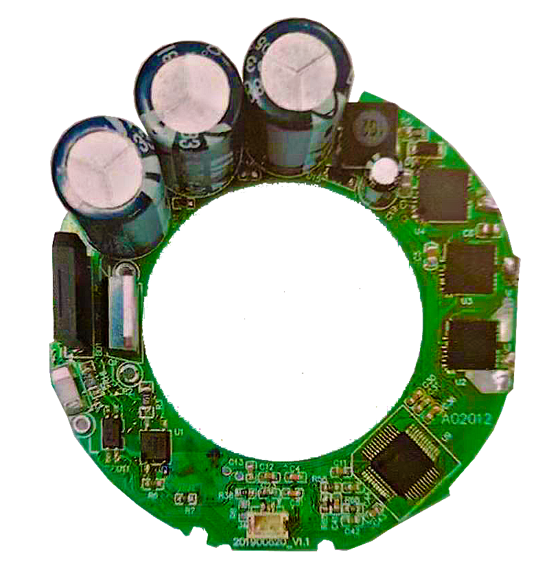
Tips for Learning MCUs
For any MCU, its basic principles and functions are largely the same; the differences lie only in the configuration and number of peripheral function modules, the instruction set, and so on.As for the instruction set, although it may appear vastly different in form, in reality only the symbols differ; the meanings they represent, the functions to be completed, and the addressing modes are basically similar.To understand an MCU, the first things to know are its ROM space, RAM space, number of I/O ports, number and timing modes of timers, peripheral function modules provided (Peripheral Circuit), interrupt sources, operating voltage, power consumption, and so on.After understanding these MCU Features, the next step is to compare the functions of the selected MCU with the functions required for actual project development, and clarify which resources are needed at present and which will not be used in the project.For functions required by the project but not provided by the selected MCU, it is necessary to carefully understand the relevant MCU documentation in order to implement them by indirect methods. For example, if the project being developed needs to communicate with the COM port of a PC but the selected MCU does not provide a UART port, an external interrupt method can be considered for implementation.For the resources required for project development, it is necessary to carefully understand and read the relevant Manual; for function modules that are not needed, they can be ignored or merely skimmed. For MCU learning, application is the key and also the main purpose.Once the relevant functions of the MCU are clearly understood, programming can begin.For beginners or designers using this MCU for the first time, there may be many unclear descriptions of MCU functions. Such issues can be resolved in two ways: one is to write special validation programs to understand the functions described in the documentation; the other is to temporarily ignore them and write the MCU program according to your current understanding, then revise and improve it during debugging. The former method is suitable for projects with a relaxed schedule and for beginners, while the latter is suitable for people with some MCU development experience or for projects with a tight schedule.Do not spend special time trying to understand the instruction set. The instruction set is only a set of symbols for logical description; during programming, you only need to consult the relevant instructions according to your own logic and the program logic requirements. As programming progresses, you will become increasingly proficient with the instruction set and may even memorize it unconsciously.There is a big difference between writing MCU programs and writing PC programs. Although C-based MCU development tools are becoming increasingly popular, for efficient program code and designers who like using assembly, assembly language remains the most concise and effective programming language.For MCU program writing, the basic framework can be broadly consistent. It is generally divided into three parts: the initialization part (this is the biggest difference between MCU program design and PC program design), the main program loop body, and interrupt handling routines. They are explained as follows:Initialization: For all MCU program design, initialization is the most basic and most important step. It generally includes the following:Mask all interrupts and initialize the stack pointer: The initialization part generally should not allow any interrupts to occur.Clear the system RAM area and display Memory: Although this may sometimes not be absolutely necessary, from the perspective of reliability and consistency, especially to prevent accidental errors, it is still recommended to develop good programming habits.I/O port initialization: According to the project application requirements, set the input/output mode of the relevant I/O ports. For input ports, set their pull-up or pull-down resistors; for output ports, their initial level output must be set to prevent unnecessary errors.Interrupt setup: For all interrupt sources required by the project, enable them and set their trigger conditions; for unused redundant interrupts, they must be disabled.Initialization of other functional modules: For all MCU peripheral function modules that need to be used, configure them according to the project application requirements. For example, for UART communication, set the Baud Rate, data length, parity mode, and Stop Bit length; for the Programmer Timer, set its clock source, prescaler, and Reload Data, etc.Parameter initialization: After completing the initialization of the MCU hardware and resources, the next step is to initialize some variables and data used in the program. This part of initialization needs to be designed according to the specific project and the overall program arrangement. For applications that use EEPROM to store project preset values, it is recommended to copy the relevant data to MCU RAM during initialization to improve the program's data access speed and reduce system power consumption (in principle, accessing external EEPROM increases power consumption).Main program loop body: Most MCUs run continuously for long periods, so their main program body is basically designed as a loop. For applications with multiple operating modes, there may be multiple loop bodies, which switch between each other via state flags. For the main program body, the following modules are generally arranged:Calculation routines: Calculation routines are generally time-consuming, so it is strongly advised against placing them in any interrupt, especially multiplication and division operations.Display transmission routines: Mainly for applications with external LED or LCD Driver.Interrupt handling routines: Interrupt routines are mainly used to handle tasks and events with high real-time requirements, such as detection of external burst signals, key detection and processing, timer counting, and LED display scanning.In general, interrupt routines should keep the code as concise and short as possible. For functions that do not require real-time processing, set a trigger flag in the interrupt and let the main program execute the specific tasks. This is very important, especially for low-power and low-speed MCUs, where timely response of all interrupts must be ensured.For the arrangement of different task bodies, different MCUs have different processing methods.For example, for low-speed, low-power MCU (Fosc=32768Hz) applications, considering that such projects are handheld devices using ordinary LCD displays and require high real-time response to key presses and display updates, timer interrupts are generally used to handle key actions and data display. For high-speed MCUs, such as applications with Fosc > 1MHz, since the MCU has enough time to execute the main program loop body, various trigger flags can be set only in the corresponding interrupts, and all tasks can be placed in the main program body for execution.In MCU program design, another point that requires special attention is to prevent the same variable or data from being accessed or set simultaneously in an interrupt and in the main program body. An effective preventive method is to arrange the processing of such data in one module and determine whether to execute the related data operation by checking the trigger flag; in other program bodies (mainly interrupts), only set the trigger flag where such data processing is needed. This ensures that data execution is predictable and unique.Note:This article is reproduced from the Internet.This article is reprinted for the purpose of conveying more information; the copyright belongs to the original author.
Zhuhai Taixin Semiconductor Co., Ltd.
Founded in 2016, Zhuhai Taixin Semiconductor Co., Ltd. is a high-tech enterprise integrating IC design and wireless intelligent communication solutions. We have successively launched long-range low-power IoT WIFI chips, low-power motor controller chips, and product solutions. The company adheres to a market-oriented approach and takes technology as its core to provide customers with high-quality chips and product technical solutions.
The company's core product: a long-range low-power IoT WIFI communication chip. This chip can be used in product fields such as smart home, security surveillance, UAV image transmission, smart meter reading, smart door locks, smart grid, smart hospitals, and logistics robots.