Before PCBs emerged, circuits were built using point-to-point wiring. This method had very low reliability because, as circuits aged, broken wires could cause open or short circuits at circuit nodes. Wire-wrapping technology represented a major advance in circuit technology; by wrapping small-diameter wire around posts at connection points, it improved circuit durability and replaceability.
As the electronics industry evolved from vacuum tubes and relays to silicon semiconductors and integrated circuits, the size and cost of electronic components continued to decrease. Electronic products increasingly appeared in consumer markets, prompting manufacturers to seek smaller and more cost-effective solutions. Thus, the PCB was born.
PCB Manufacturing Process
PCB manufacturing is highly complex. Taking a four-layer printed circuit board as an example, the process mainly includes PCB layout, core board fabrication, inner-layer PCB layout transfer, core board drilling and inspection, lamination, drilling, chemical copper deposition on hole walls, outer-layer PCB layout transfer, and outer-layer PCB etching.
1. PCB Layout
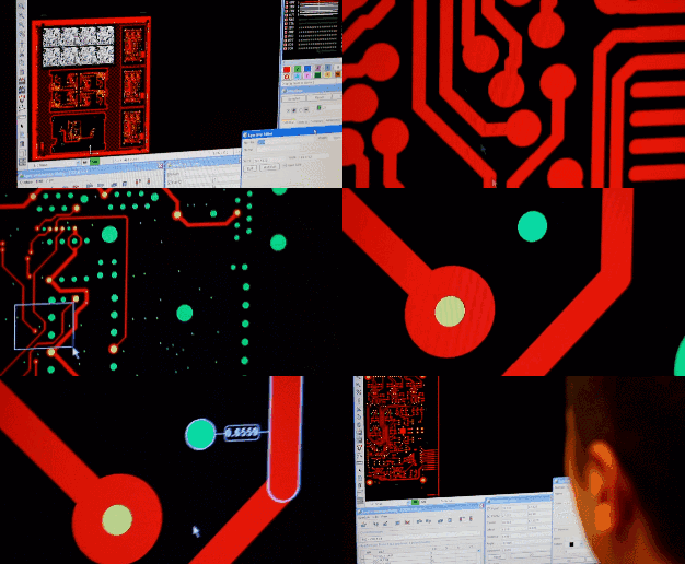
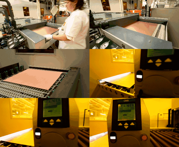
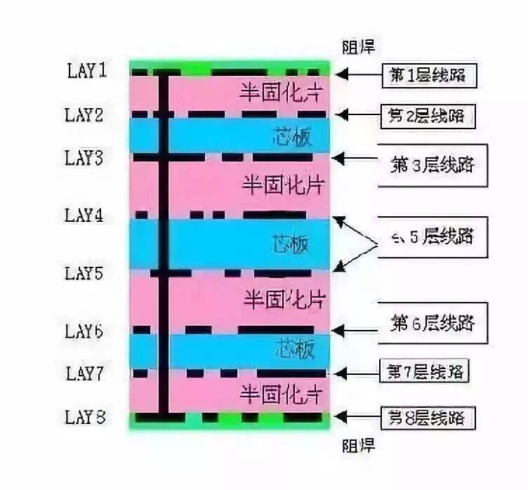
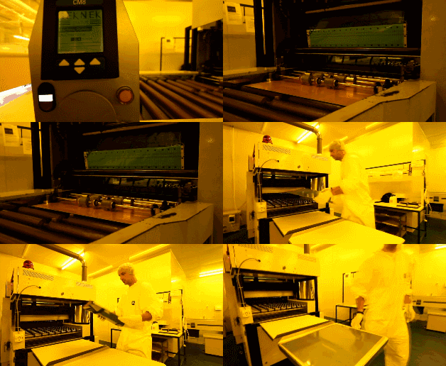
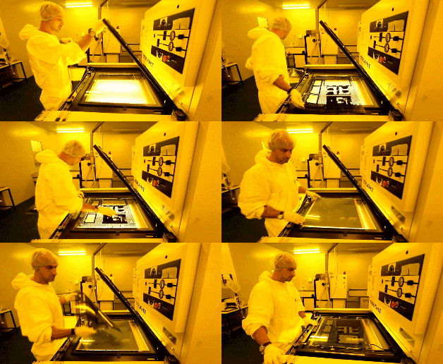
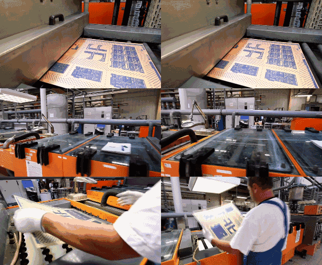
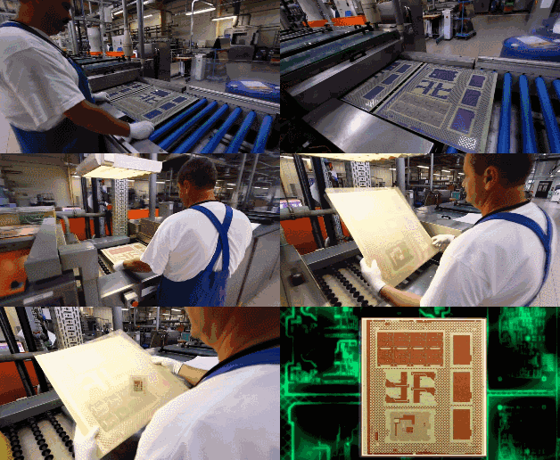
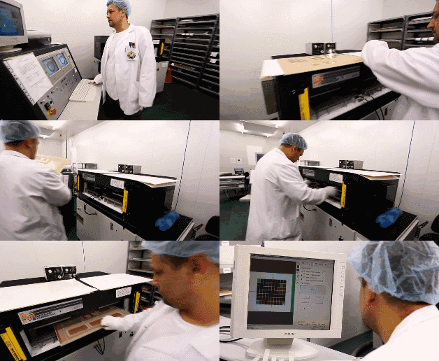
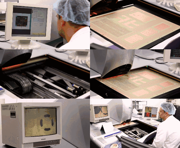
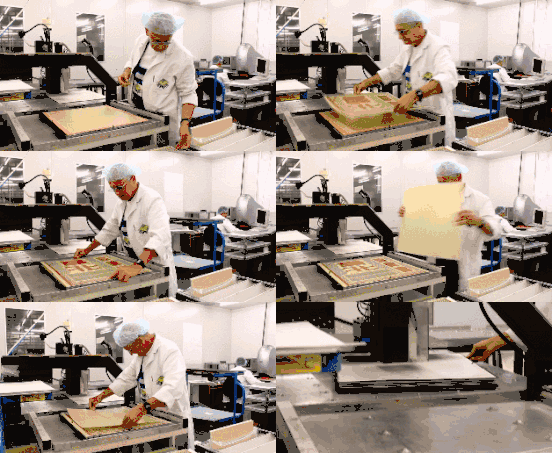
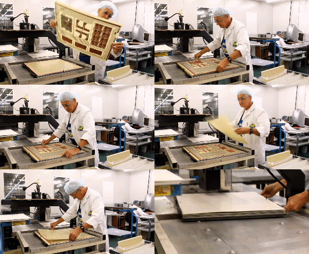
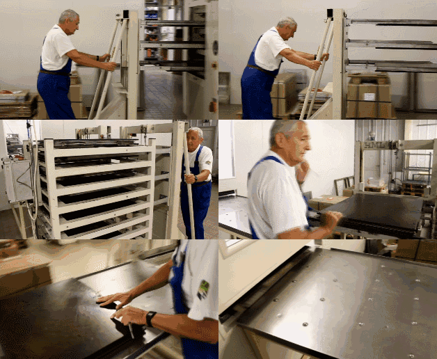
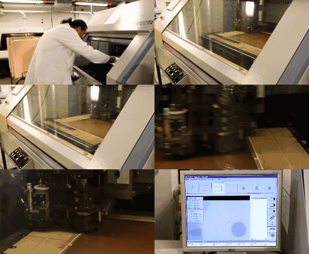
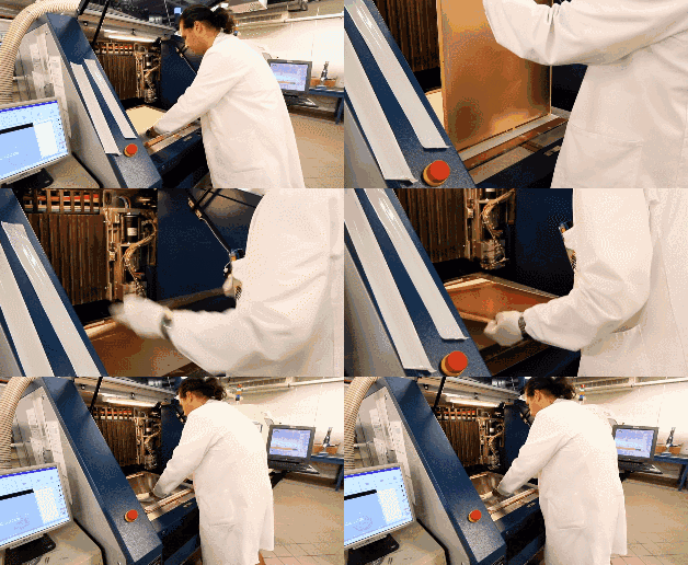
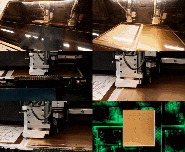
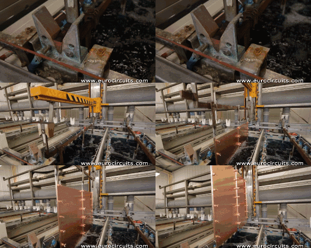
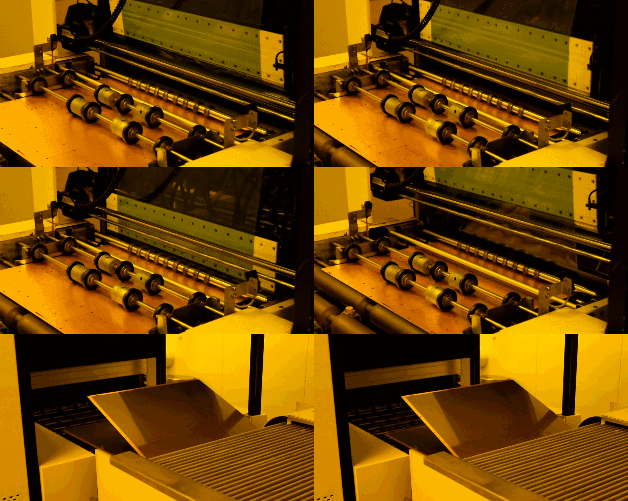
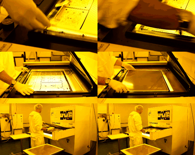
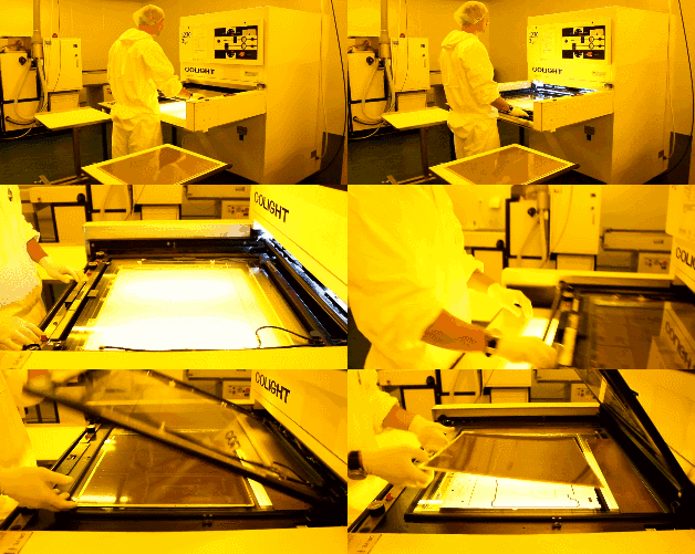
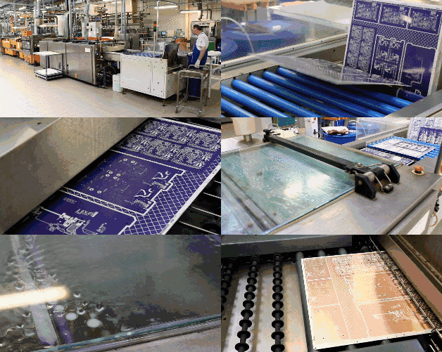
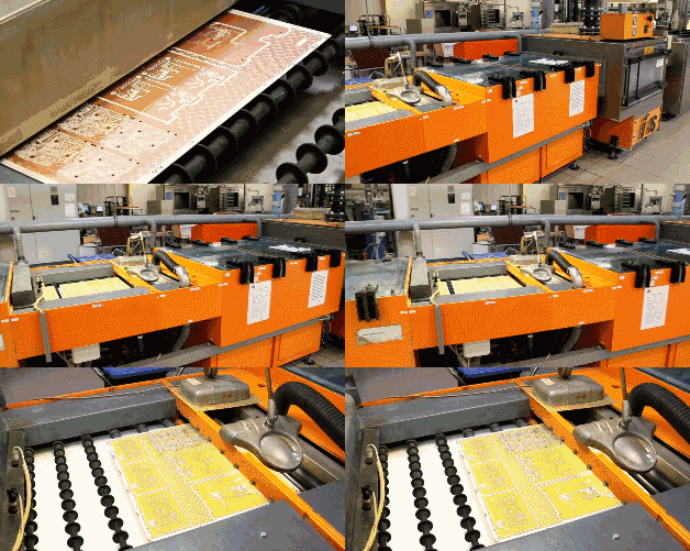
The first step in PCB manufacturing is to organize and inspect the PCB layout. The PCB fabrication factory receives CAD files from the PCB design company. Because each CAD software has its own unique file format, the PCB factory converts them into a unified format—Extended Gerber RS-274X or Gerber X2. The factory's engineers then check whether the PCB layout is compatible with the manufacturing process and whether there are any defects or other issues.2. Core Board FabricationClean the copper-clad laminate; dust can cause short circuits or open circuits in the final board.The figure below shows an example of an 8-layer PCB. It is actually made from three copper-clad laminates (core boards) plus two copper foils, bonded together with prepreg. Fabrication starts with the innermost core board (layers 4 and 5) and proceeds by stacking and securing the layers successively. Four-layer PCB fabrication is similar, except that only one core board plus two copper foils are used.3. Inner-Layer PCB Layout Transfer: First, the two circuit layers of the innermost core board must be fabricated. After the copper-clad laminate is cleaned, a photosensitive film is applied to its surface. This film cures when exposed to light, forming a protective layer on the copper foil of the copper-clad laminate.Place the two PCB layout films and the double-sided copper-clad laminate, then finally insert the upper PCB layout film, ensuring precise alignment of the upper and lower PCB layout films.The exposure machine uses UV lamps to irradiate the photosensitive film on the copper foil. Under the transparent areas of the film, the photosensitive film cures; under the opaque areas, the photosensitive film remains uncured. The copper foil beneath the cured photosensitive film is the required PCB layout circuitry, functioning like the toner of a laser printer in handmade PCBs.Then an alkaline solution is used to wash away the uncured photosensitive film; the required copper circuitry remains covered by the cured photosensitive film.Then a strong alkali, such as NaOH, is used to etch away the unwanted copper foil.Peel off the cured photosensitive film to expose the required PCB layout copper circuitry.4. Core Board Drilling and InspectionThe core board has now been fabricated. Next, alignment holes are drilled in the core board to facilitate alignment with other materials. Once the core board is pressed together with other PCB layers, it cannot be modified, so inspection is very important. Machines automatically compare it with the PCB layout drawings to check for errors.A new material called prepreg is required here. It is the adhesive between core boards (for PCBs with more than 4 layers) and between core boards and outer copper foils, and it also provides insulation.The lower copper foil and two layers of prepreg have already been positioned through the alignment holes and fixed to the lower steel plate. Then the fabricated core board is also placed into the alignment holes, and finally two layers of prepreg, one layer of copper foil, and one layer of pressure-bearing aluminum plate are successively placed over the core board.The PCB boards clamped by steel plates are placed on a rack and then sent into a vacuum hot press for lamination. The high temperature in the vacuum hot press melts the epoxy resin in the prepreg, bonding the core boards and copper foils together under pressure.After lamination is complete, remove the upper steel plate that pressed the PCB. Then remove the pressure-bearing aluminum plates; the aluminum plates also serve to separate different PCBs and ensure that the outer copper foil of the PCB is smooth. The PCB removed at this point is covered on both sides with a layer of smooth copper foil.To connect the four non-contacting copper foil layers in the PCB, through-holes must first be drilled from top to bottom to penetrate the PCB, and then the hole walls must be metallized to conduct electricity.An X-ray drilling machine is used to locate the inner-layer core board. The machine automatically finds and positions the hole locations on the core board, then drills alignment holes in the PCB to ensure that subsequent drilling passes exactly through the center of the hole locations.Place a layer of aluminum plate on the drilling machine table, then place the PCB on top. To improve efficiency, depending on the number of PCB layers, one to three identical PCBs are stacked together for drilling. Finally, cover the topmost PCB with a layer of aluminum plate. The upper and lower aluminum plates prevent the drill bit from tearing the copper foil on the PCB as it enters and exits.During the previous lamination process, melted epoxy resin was squeezed out of the PCB, so it needs to be trimmed. A profile milling machine cuts the outer perimeter of the PCB according to the correct XY coordinates.7. Chemical Copper Deposition on Hole WallsBecause almost all PCB designs use through-holes to connect circuits on different layers, a good connection requires a 25-micron copper film on the hole walls. Copper films of this thickness must be achieved by electroplating, but the hole walls consist of non-conductive epoxy resin and glass fiber board.Therefore, the first step is to deposit a conductive substance on the hole walls. Through chemical deposition, a 1-micron copper film is formed over the entire PCB surface, including the hole walls. The entire process, including chemical treatment and cleaning, is controlled by machines.8. Outer-Layer PCB Layout Transfer
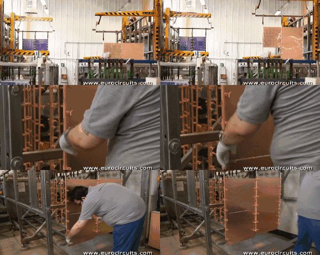
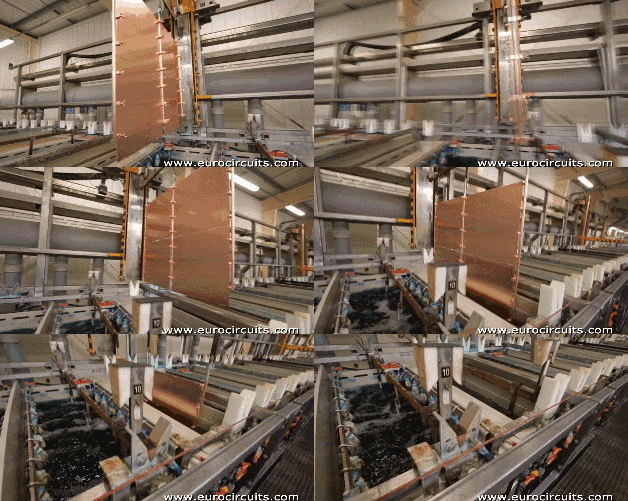
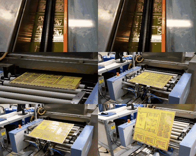
Next, the outer-layer PCB layout is transferred to the copper foil. The process is similar to the previous inner-layer core board PCB layout transfer: both use photographic film and photoresist film to transfer the PCB layout onto the copper foil. The only difference is that positive film is used for board fabrication.The inner-layer PCB layout transfer uses the subtractive method and negative film for board fabrication. On the PCB, the areas covered by cured photoresist are the circuitry. After the uncured photoresist is removed, the exposed copper foil is etched, while the PCB layout traces remain protected by the cured photoresist.The outer-layer PCB layout transfer uses the normal method and positive film for board fabrication. On the PCB, the areas covered by cured photoresist are the non-circuit areas. After the uncured photoresist is removed, electroplating is performed. Electroplating cannot occur where the film remains; in areas without film, copper is plated first and then tin. After resist stripping, alkaline etching is performed, and finally the tin is stripped. The circuit pattern remains on the board because it is protected by the tin.The PCB is held with clips, and copper is electroplated onto it. As mentioned earlier, to ensure sufficiently good conductivity in the holes, the copper film plated on the hole walls must be 25 microns thick, so the entire system is automatically controlled by a computer to ensure accuracy.9. Outer-Layer PCB EtchingNext, the etching process is completed by a fully automated production line. First, the cured photoresist on the PCB is removed. Then a strong alkali is used to remove the unwanted copper foil covered by it. Next, a tin stripping solution is used to remove the tin plating from the PCB layout copper foil. After cleaning, the 4-layer PCB layout is complete.Disclaimer:This article is reprinted from the Internet, and the purpose of reprinting this article is to convey more information. The copyright belongs to the original author.
- END -