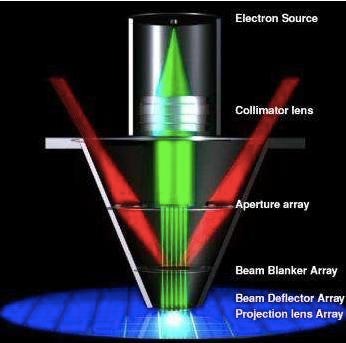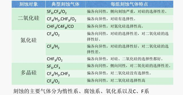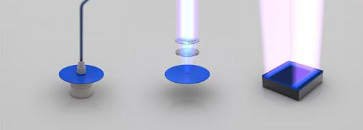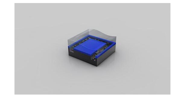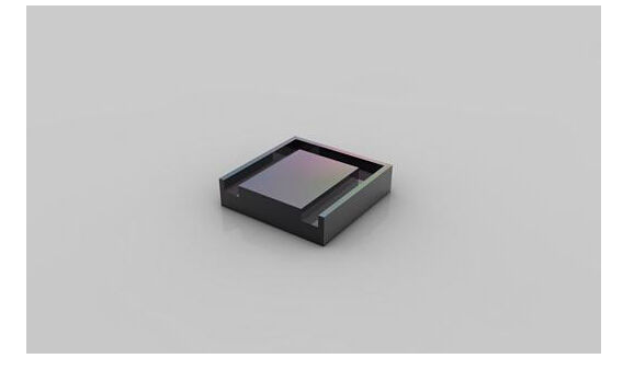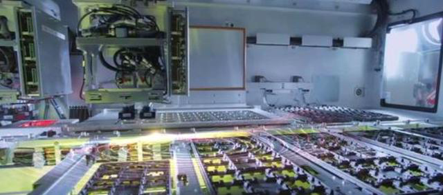
Transistors are not literally installed. Chip manufacturing actually consists of processes from sand to wafers and from wafers to chips. Before chip manufacturing, IC design is responsible for completing the chip design, which is then handed to a wafer foundry.
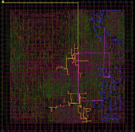
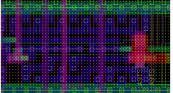
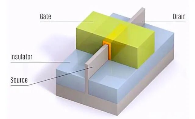
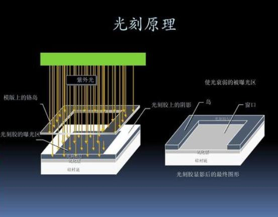
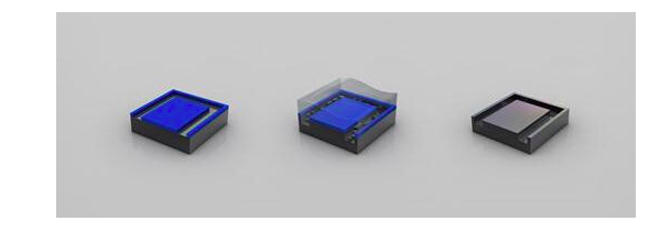
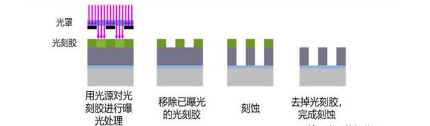
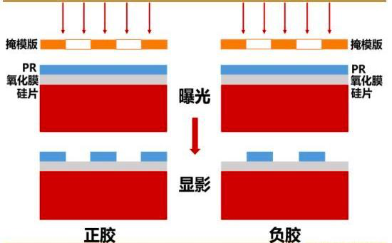
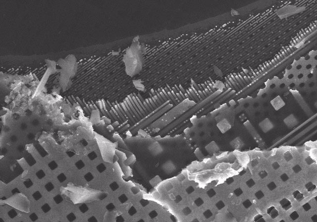
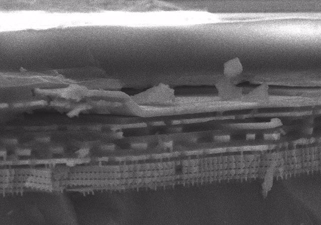
Chip design is divided into front-end design and back-end design. There is no unified, strict boundary between front-end design (also called logic design) and back-end design (also called physical design); design involving process-related work is back-end design. Chip design requires professional EDA tools.If we magnify the designed gate circuit, the white dots are the substrate, and some green borders are the doped layers.Once the chip design is complete, it must be manufactured. Transistors are directly carved out on the wafer. The larger the wafer and the smaller the chip process node, the more chips can be cut from it, and the higher the efficiency.For example, it is like cutting a watermelon: if the watermelon is larger, but the pieces were originally cut into 3 cm chunks and now are cut into 2 cm chunks, wouldn’t there be more pieces? That is why wafers have progressed from 2 inches, 4 inches, 6 inches, and 8 inches to today’s 16-inch size.The concept of a process node actually refers to the size of the gate, also called gate length. The shorter this distance, the more transistors can fit, so chips do not become larger as technology advances; with more advanced manufacturing processes, chip area and power consumption become smaller. However, if we make the gate smaller, the current flowing between the source and drain becomes faster, and the process difficulty increases.Chip manufacturing is divided into seven major production areas: diffusion, photolithography, etching, ion implantation, thin-film growth, polishing, and metallization.Among them, the two most important steps for carving the wafer are photolithography and etching. Photolithography is a precision microfabrication technology.Conventional photolithography uses ultraviolet light with a wavelength of 2000–4500 as the image information carrier and a photoresist as the intermediate (image-recording) medium to realize pattern transformation, transfer, and processing, ultimately transferring the image information to a wafer (mainly a silicon wafer) or dielectric layer.Photolithography is the process of creating the circuits and functional areas required for chip fabrication. Simply put, it “prints” the circuits and functional areas designed by chip designers onto the wafer, similar to taking a photograph with a camera.The photos taken by a camera are printed onto film, whereas what photolithography prints is not a photo but circuit patterns and other electronic components.Etching technology uses chemical or physical methods to remove the unmasked wafer surface or dielectric layer not covered by the thin resist layer, thereby obtaining a pattern on the wafer surface or dielectric layer that exactly matches the pattern of the thin resist layer.The functional layers of an integrated circuit overlap in three dimensions, so the photolithography process is always repeated multiple times. For example, a large-scale integrated circuit may require about 10 photolithography steps to complete the transfer of patterns for all layers.There are two basic etching processes in semiconductor manufacturing: dry etching and wet etching.At present, dry etching is still the mainstream process; equipment that uses dry etching is called a plasma etcher.Integrated circuit manufacturing requires various types of dry etching processes, involving a wide range of materials on the silicon wafer. The materials to be etched mainly include dielectrics, silicon, and metals. Through repeated coordination with processes such as photolithography and deposition, complete underlying circuits, gates, insulating layers, and metal interconnects can be formed.A photomask prepared in advance is placed over a wafer (also called a silicon wafer) coated with photoresist, and then the wafer is irradiated with ultraviolet light through the photomask for a certain period. The principle is to use ultraviolet light to alter part of the photoresist so that it becomes easier to remove.Dissolving the photoresist:During photolithography, the photoresist exposed to ultraviolet light is dissolved; after removal, the remaining pattern matches that on the mask.“Etching” follows photolithography: an etchant is used to remove the deteriorated portion of the photoresist (positive resist), revealing the patterns of the semiconductor devices and their connections on the wafer surface. Another etchant is then used to etch the wafer, forming the semiconductor devices and their circuits.Removing the photoresist:After etching is complete, the photoresist has fulfilled its purpose; once it is fully removed, the designed circuit pattern becomes visible.A note here:What Is Photoresist?We need to understand that the circuit design is first written onto a photomask by laser; then a light source shines through the mask onto the surface of a silicon wafer coated with photoresist, causing a chemical reaction in the exposed areas of the photoresist. Development technology is then used to dissolve and remove either the exposed or unexposed areas, transferring the circuit pattern on the mask to the photoresist. Finally, etching technology transfers the pattern to the silicon wafer.Photolithography is divided into two basic processes—positive photolithography and negative photolithography—depending on whether positive or negative resist is used. In positive photolithography, the structure of the exposed portion of the positive resist is destroyed and washed away by the solvent, so the pattern on the photoresist is the same as that on the photomask.Conversely, in negative photolithography, the exposed portion of the negative resist hardens and becomes insoluble, while the masked portion is washed away by the solvent, so the pattern on the photoresist is the inverse of that on the photomask.It can be said that in wafer manufacturing, circular silicon wafers 30 cm in diameter shuttle among various extremely precise processing equipment, which create trenches or circuits on the wafer surface only one-thousandth the diameter of a human hair.Thermal processing, photolithography, etching, cleaning, deposition... Each wafer must be continuously processed day and night for two months, going through hundreds or thousands of process steps, ultimately integrating massive numbers of tiny electronic devices. After dicing and packaging, it becomes the cornerstone of the information society—the chip.This is a top-down SEM image, in which the layered structure inside the CPU can be seen very clearly. The deeper the layer, the narrower the line width, and the closer it is to the device layer.This is a cross-sectional view of the CPU, clearly showing the layered CPU structure. There are approximately 10 layers from top to bottom, and the bottommost layer is the device layer, namely the MOSFET transistors.This article is reproduced from “RF Aesthetics”, if there is any infringement, please contact us.
Zhuhai Taixin Semiconductor Co., Ltd.
Zhuhai Taixin Semiconductor Co., Ltd. was founded in 2016 and is a high-tech enterprise integrating integrated circuit design and wireless intelligent communication solutions. We have successively launched long-range, low-power IoT WIFI chips, low-power motor controller chips, and related product solutions. The company adheres to a market-oriented approach with technology as its core, providing customers with high-quality chips and product technical solutions.
The company's core product is a long-range, low-power IoT WIFI communication chip. This chip can be used in product fields such as smart home, security monitoring, UAV video transmission, smart meter reading, smart door locks, smart grids, smart hospitals, and logistics robots.